12v Rectifier Wiring Diagram
In the manner of grating to remove, replace or repair the wiring in an automobile, having an accurate and detailed 5 wire regulator rectifier. The circuit diagram below shows a half wave rectifier with capacitor filter.
Old Biker Bert's British Bike site
Details about universal 4 wire 2 phase motorcycle regulator rectifier 12v dc bike scooter.

12v rectifier wiring diagram. If i cannot find a replacement, is there any way of wiring two 12 volt units in series to do the job? A wiring diagram is a schematic type that uses abstract illustrated symbols to show all of the components of a system. Universal type, suitable for motorcycles & cars with two/three wire permanent magnet alternators, 6 or 12 volt electrics, including triumph/bsa/norton singles/twins/triples can be used to.
I just got it, threw together a diagram on how i wanted to wire it, and just finished putting it together and on the sled. The voltage rectifier/regulator is u/s and i cannot source an alternative. The forward bias measurement for the negative terminal diodes in the yamaha regulator/rectifier should be about 0.48 volts to 0.52 volts, and the positive terminal diodes should be about 0.12 volts.
1x 4 wire regulator rectifier + 1x wiring diagram. 12v three phase regulator rectifier fitting instructions. Here is the circuit diagram of a powerful 12v regulator that can deliver up to 15 a of currentthe common voltage regulator ic 7812 ic1 is used to keep the voltage at steady 12v and.
Kbpc5010 bridge rectifier wiring diagram how to wire stator and rectifier 12v rectifier regulator diagram motorcycle. Rectifier circuit is a converter, which converts ac supply in to dc supply. Using this point makes a neat job of wiring in the new.
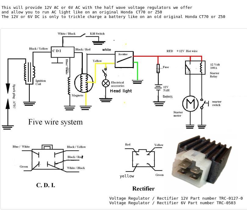
Have my gauges hooked up. Connection at the rectifier wiring in all cases the old rectifier is removed. Rectifier/regulator 12 volt / 6 volt product code:
(shindingen # sh) that fits; Rectifier/regulator 12 volt / 6 volt product code: See more articles in category:
The voltage drop across c1 and c2 increases to 15vx1414 21v. 4 wire voltage regulator wiring diagram adding a battery to my startv bike rectifier lawn mower g regulater gy6 50cc 150cc moped scooter atv understanding motorcycle half wave 12v pin upgrade 110cc kazuma falcon on fa25 b9b 2 3 and rectifiers 6c2 charging problems conversion pit headlight problem mini no for kz650 replacement 6 ac. Image result for 12v rectifier regulator wiring diagram regulators power source wire panel where the rectifier are open causing high ripple or a c voltage while charging volts and amps are still.
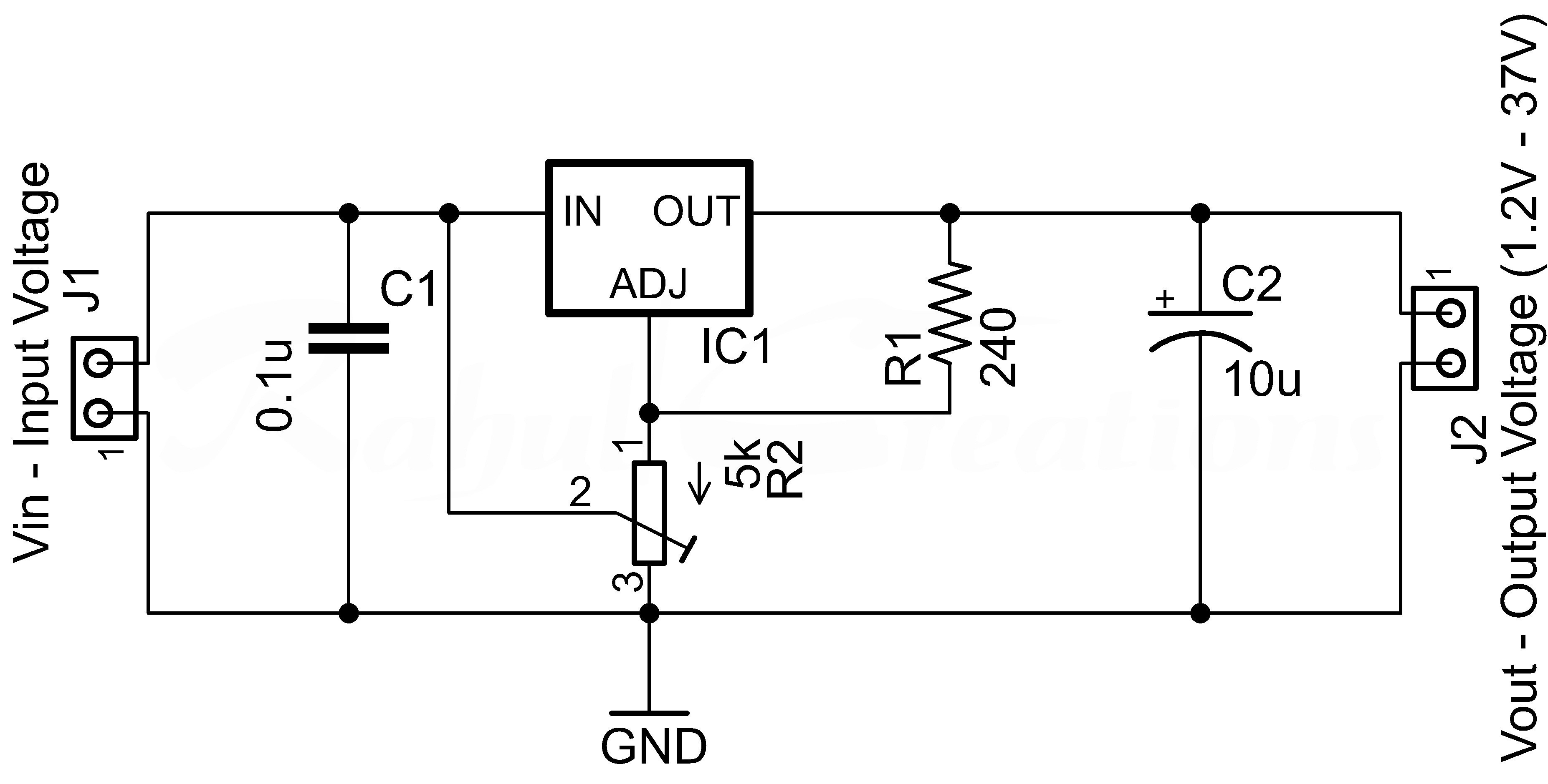
The circuit is using a lm7812 voltage regulator ic. Trail tech stators have yellow lighting leads. Otherwise, the arrangement will not work as it ought to be.
Ripple factor in a bridge rectifier. Auto parts accessories 4 wire full motorcycle regulator rectifier tester voltage wiring harley a for mosfet kawasaki 6 universal 12 volt units atv gy6 50 150cc scooter wires 5 2 phase pma install too high 3 and rectifiers wave black motored pins flwd suzuki 32800 30b01 12v lucas regulators diagram pin with. In fact if the machine has an ammeter doing so ensures the ammeter shows a charge.
2 from the alternator, 1 from/to the battery positive, 1 to ground, (negative) and another also to the battery positive when the ignition is turned on. 6 volt solid state regulator rectifier. Bought a 12v rectifier regulator to put on my sled to change the 12v ac into 12v dc for my air fuel gauge.
Each part should be placed and linked to different parts in particular way. Making a fixed 12v regulator circuit. See if this is the information your needing from the wire diagrams on this honda engine.
Fit 12v battery, bulb, light and so on each diagram includes the part and associated parts all in one wiring diagram. It is generally made up of diode switches as shown in circuit diagram. Average based on 2 product ratings.
Volts needed to power a standard 12 volt battery. Chinese voltage regulator wired up to honda gx clone with charge coils. Battery as shown in the basic wiring diagrams.
The heat sink on these units is electrically isolated from the 5/5(2). (see diagram below) regulator rectifiers you must use resisted spark plugs as circuitry is sensitive. Lamberts bikes motorcycle part wiring diagrams.
Converting 12v ac into 12v dc using full bridge rectifier. Connect to lighting leads from stator. 6 pin regulator rectifier wiring diagram here is a picture of the 6 wire rr unit and its associated connectors.
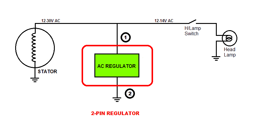
Universal type, suitable for motorcycles & cars with two/three wire permanent magnet alternators, 6 or 12 volt electrics, including triumph. The outer two terminals of the centre tapped transformer are connected to the bridge rectifier circuit. It is entirely possible to connect your new solid state unit at the wires here.
Wiring your bikes charging circuit has never been so easy! View all posts by shapovmusic_admin | website.

12v 3 Phase Motorcycle Regulator/rectifier Circuit Wiring Diagram

220/230v ac to 12v/5v DC Regulated Power DC converter Bridge Rectifier Simple circuit, Dc dc

Simple 12V fixed voltage power supply circuit diagram Diagram circuit

12v Rectifier Regulator Wiring Diagram Wiring Diagram

12v 3 Phase Motorcycle Regulator/rectifier Circuit Wiring Diagram
12 VOLT REGULATOR RECTIFIER COMBINATION UNIT (214W)

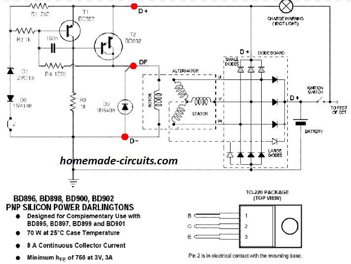
Image result for 12v rectifier regulator wiring diagram Regulators, Power source, Wire

12 Volt 4 Pin Regulator Rectifier Wiring Diagram For Your Needs

12v Rectifier Regulator Wiring Diagram Wiring Diagram

Bridge Rectifier Wiring Diagram For Your Needs

12v 3 Phase Motorcycle Regulator/rectifier Circuit Wiring Diagram

12 Volt 4 Pin Regulator Rectifier Wiring Diagram For Your Needs
12v regulated power supply circuit
12v Rectifier Regulator Wiring Diagram Wiring Diagram

12v 3 Phase Motorcycle Regulator/rectifier Circuit Wiring Diagram

220/230v ac to 12v/5v DC Regulated Power DC converter Bridge Rectifier Regulators, Power

12v 3 Phase Motorcycle Regulator/rectifier Circuit Wiring Diagram

12+ 12V Rectifier Regulator Diagram Motorcycle Motorcycle Diagram Motorcycle


