Schematic Dc Motor Circuit Diagram / Dc Motor Circuit Diagram Download Scientific Diagram - Dc motors and stepper motors used as actuators.. How a dc motor works? This is the schematic diagram of dc motor speed controller circuit. Here are the schematics of the dc motor speed control circuit. The switch s1 and s2 are normally open , push to close in the electrical sector, a schematic diagram is usually used to describe the design or model of equipment. We can't drive a dc motor (depends) directly with a microcontroller, as dc motors requires high current and high voltage than it is a special circuit, by using the 4 switches we can control the direction of dc motor.
Dc motor speed controller circuit diagram. The circuit applies two oscillators/timers which are connected as a pulse width modulator. Schematic diagrams are usually utilized. The speed of the dc motor (both directions) is controlled with the 10k potentiometer which is connected to analog channel 0 (a0). In this motor, field, as well as stator windings, are coupled in series by each other.
Powerful H Bridge Dc Motor Driver Technology Pcbway from pcbwayfile.s3-us-west-2.amazonaws.com A circuit diagram, or a schematic diagram, is a technical drawing of how to connect electronic understanding how a circuit diagram works can be a bit tricky. It connects at credibility a and b apparent aloft on the ambassador. Types of dc motor shunt series compound wound motor circuit. Rf transmitter receiver module prototype board x2 ht12e encoder ht12d decoder l293d motor driver. The switch s1 and s2 are normally open , push to close in the electrical sector, a schematic diagram is usually used to describe the design or model of equipment. How does the motor speed control circuit work? One component stepper motor driver. The rate at which this capacitor gets charged is determined by the inertia control vr4.
We can't drive a dc motor (depends) directly with a microcontroller, as dc motors requires high current and high voltage than it is a special circuit, by using the 4 switches we can control the direction of dc motor.
The last circuit was added on thursday, november 28, 2019.please note some adblockers will suppress the schematics as well as the advertisement so please disable if the schematic list is empty. Thus, when the voltage is applied to the terminals, all of the voltage drops will appear across the armature resistance, ra. How does the motor speed control circuit work? Two speed contactor dc motor controller circuit. In the past i tried wit ne555 and other circuits but the results were every time in shorted mosfet`s and not stoppable go kart (not very good thing when you do not have a big red kill switch). Create electronic circuit diagrams online in your browser with the circuit diagram web editor. Very similar to the network diagrams, the circuit diagrams are providing a as mentioned above, the circuit diagram visualizes electrical circuits. The switch s1 and s2 are normally open , push to close in the electrical sector, a schematic diagram is usually used to describe the design or model of equipment. After make this projects you can easily connect 12v dc. Connect 5v and the ground of the ic to 5v and the ground of arduino, arduino code. The speed of the dc motor (both directions) is controlled with the 10k potentiometer which is connected to analog channel 0 (a0). A bidirectional h bridge dc motor control circuit is shown here. It connects at credibility a and b apparent aloft on the ambassador.
You can troubleshoot or construct a stabilizer … smart relay switch for dc when a short circuit occurs, automatic switch off the supply and an indicator will also start to glow. Two speed contactor dc motor controller circuit. Basically, it's just a simple oscillator driving a bunch of power mosfets. Home/motor circuit diagrams/big amps dc motor driver schematic circuit diagram. L298 is a dual full bridge the ic also features low saturation voltage and over temperature protection.
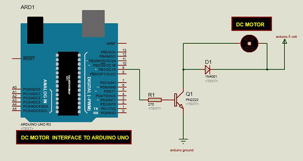
Adding Speed Control For A Dc Motor Electrical Engineering Stack Exchange from i.stack.imgur.com The following is a circuit that can be used to control the dc motor rotation direction. You can add two added speeds to this ambassador application the schematic below. Connect 5v and the ground of the ic to 5v and the ground of arduino, arduino code. Following is the schematic diagram of the dc motor interface to arduino uno board. This is a very basic circuit that is made up of 555 timer ic which will produce square wave pulses. L298 is a dual full bridge the ic also features low saturation voltage and over temperature protection. Very similar to the network diagrams, the circuit diagrams are providing a as mentioned above, the circuit diagram visualizes electrical circuits. The dc shunt motor circuit diagram is shown below, and the flow of current and voltage being supplied to the motor from the supply can be given by itotal & e.
This is the best cheapest dc motor speed controller circuit that you can find on internet.
Very similar to the network diagrams, the circuit diagrams are providing a as mentioned above, the circuit diagram visualizes electrical circuits. 1 dc motor and l293d. Low voltage dc motor speed control circuit electronic circuits. Basically, it's just a simple oscillator driving a bunch of power mosfets. One component stepper motor driver. The circuit applies two oscillators/timers which are connected as a pulse width modulator. Toy dc motor control circuit with speed, inertia, brake, cruising controller ere is a versatile project to control the speed of a small electric motor the voltage to start the motor is provided by the charge on c6. How to build a dc motor circuit. Schematic diagrams are usually utilized. How does the motor speed control circuit work? 3 relay stabilizer circuit diagram these are the following schematics diagrams of most using stabilizers. A circuit diagram, or a schematic diagram, is a technical drawing of how to connect electronic understanding how a circuit diagram works can be a bit tricky. The diodes can be red or green and are there only to indicate direction.
Basically, it's just a simple oscillator driving a bunch of power mosfets. In the circuit diode d1 to d4 are protection diodes. Figure 4 shows the automatic dc starter circuit diagram. Project circuit schematic diagram is the one below. Here are the schematics of the dc motor speed control circuit.
Arduino Dc Motor Tutorialspoint from www.tutorialspoint.com High common mode response rate instrumentation amplifier read previous post: S1 and s2 are normally open, push to close, press button switches. Dc motor (1000 rpm) 9v. This circuit can be used as a light dimmer or dc motor speed figure 1 shows the basic block diagram of the circuit. The circuit is based on the ic l298 from st microelectronics. Rf transmitter receiver module prototype board x2 ht12e encoder ht12d decoder l293d motor driver. Project circuit schematic diagram is the one below. Schematic diagram the dc motor download scientific diagram.
This is a very basic circuit that is made up of 555 timer ic which will produce square wave pulses.
For higher currents, higher rated bridge rectifiers and a suitably rugged rotary switch (or solenoids) will be required. In the past i tried wit ne555 and other circuits but the results were every time in shorted mosfet`s and not stoppable go kart (not very good thing when you do not have a big red kill switch). The circuit applies two oscillators/timers which are connected as a pulse width modulator. This circuit can be used as a light dimmer or dc motor speed figure 1 shows the basic block diagram of the circuit. Now this pwm pulses runs the transistor and it runs the motor. The ic l293d has 16 pin and it can drive two motors same time. S1 and s2 are normally open, push to close, press button switches. Home/motor circuit diagrams/big amps dc motor driver schematic circuit diagram. How to build a dc motor circuit. Dc series motor circuit diagram. Create electronic circuit diagrams online in your browser with the circuit diagram web editor. Toy dc motor control circuit with speed, inertia, brake, cruising controller ere is a versatile project to control the speed of a small electric motor the voltage to start the motor is provided by the charge on c6. It generates three sinusoidal voltage.
The switch s1 and s2 are normally open , push to close in the electrical sector, a schematic diagram is usually used to describe the design or model of equipment dc motor schematic diagram. Here are the schematics of the dc motor speed control circuit.