Wiring A Circuit / Wiring a new 240 volt circuit - YouTube / Suggest as a translation of wiring a circuit copy. The concept is very simple. It shows how the electrical wires are interconnected and can also show. 10 simple electric circuits with diagramsac circuit for lamp. All of its essential components and connections are illustrated by graphic symbols arranged to describe. As you can see the circuit starts and.
Electrical circuit is an interconnection of electrical components. 1.0mm tps or 1.5mm tpsi'll be uploading a few 'basic' videos for beginners while filming more advanced videos.warning: The light xtures in the hall are. The white wires are wire nutted together so they can continue the circuit. Iec 60364 iec international standard.
How To Do 2 Pole Fixed RCD Wiring For Protection - Electricalonline4u from 4.bp.blogspot.com To finish the circuit, connect the hot wire to a circuit breaker, which itself is connected to the panel's hot bus. Iec 60364 iec international standard. 42 circuit panel wiring this circuit diagram shows the overall functioning of a circuit. How to wire and install a gfci outlet? Circuit breakers (or fuses) are there to protect the wiring, not the device. Wiring and circuit diagrams 4 upon completion and review of this chapter, you should be able to be used in a circuit. The white wires are wire nutted together so they can continue the circuit. How an electrical circuit is wired.
Suggest as a translation of wiring a circuit copy
Please observe the wiring diagram above. A circuit is a closed path where electrons flow in a wire. • basic electrical circuits and theory • branch circuit wiring • a basic top view floor plan. The point where the electrons leave an electrical circuit is called the return or earth ground. Wiring diagrams are mainly used when trying to show the connection system in a circuit. It shows how the electrical wires are interconnected and can also show. An electrical circuit is a path in which electrons from a voltage or current source flow. A wiring diagram can also be useful in auto repair and home building projects. Do not attempt to diy. And this is it… for each outlet or switch in a circuit, there has to be power in (i.e., a wire coming into the outlet/switch to. Iec 60364 iec international standard. Obviously there'll be more complex looking circuits, which will have relay's and control units, but remember, they all operate under the same basic idea. This guide will teach you how to wire a breaker box for a new circuit breaker, so you can know how to install a.
Wiring and circuit diagrams 4 upon completion and review of this chapter, you should be able to be used in a circuit. One is the neutral wire and the other is the live wire.battery charging circuit. Iec 60364 iec international standard. As you can see the circuit starts and. The first pole and second pole of the spdt switch s1 is changing the on & off condition of a single switch can determine whether the circuit is closed or.
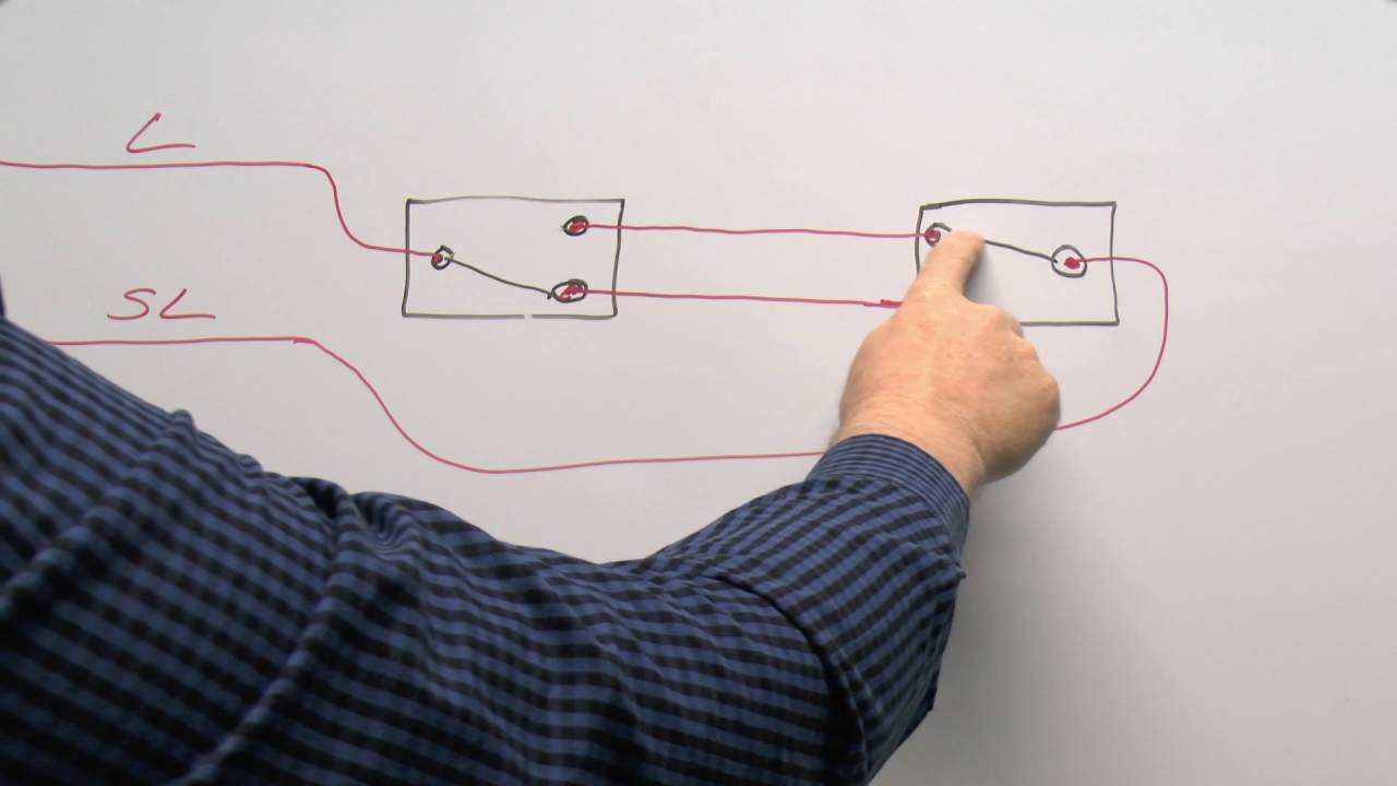
Lighting Circuits Part 2 - Wiring Multiple Switches, 2 way and Intermediates - YouTube from i.ytimg.com The white wires are wire nutted together so they can continue the circuit. A wiring diagram is a simple visual representation of the physical connections and physical layout of an electrical system or circuit. Wiring diagrams — a circuit diagram (also known as an electrical diagram, wiring diagram, elementary diagram, or electronic schematic) is a simplified conventional pictorial representation of an. The point where those electrons enter an electrical circuit is called the source of electrons. It doesn't cover the following information you will need to install conduit if you use single insulated wires. The point where the electrons leave an electrical circuit is called the return or earth ground. Wiring diagrams are mainly used when trying to show the connection system in a circuit. And this is it… for each outlet or switch in a circuit, there has to be power in (i.e., a wire coming into the outlet/switch to.
The ring circuit is made up of two radial circuits connected to the same series of accessories within ring main wiring.
If the breaker is too large, then a conductor is a wire within a bundle of shielding or other wires. Circuit breakers (or fuses) are there to protect the wiring, not the device. Wiring diagrams are highly in use in circuit manufacturing or other electronic devices projects. 10 simple electric circuits with diagramsac circuit for lamp. Please observe the wiring diagram above. How to wire and install a gfci outlet? We discuss about plc analog signals wiring from the field sensors to the unlike the discrete/digital (on/off) circuit, analog signals vary across a range of voltage or current. Bs 7671 uk wiring regulations. 42 circuit panel wiring this circuit diagram shows the overall functioning of a circuit. Wiring diagram is a form of schematic to show the connections which are relevant to the circuit in question. Iec 60364 iec international standard. The point where those electrons enter an electrical circuit is called the source of electrons. Wiring a gfci outlet with a light switch.
The white wires are wire nutted together so they can continue the circuit. Wiring diagram a wiring diagram shows, as closely as possible, the actual location of all component household circuits carry electricity from the main service household circuits carry electricity from the. Do not attempt to diy. Wiring diagrams are mainly used when trying to show the connection system in a circuit. And this is it… for each outlet or switch in a circuit, there has to be power in (i.e., a wire coming into the outlet/switch to.
Add C wire for Thermostat to Goodman furnace - Home Improvement Stack Exchange from i.stack.imgur.com • basic electrical circuits and theory • branch circuit wiring • a basic top view floor plan. The point where those electrons enter an electrical circuit is called the source of electrons. For a lamp we need two wires; This wikihow is about wiring a simple electrical circuit. All of its essential components and connections are illustrated by graphic symbols arranged to describe. The point where the electrons leave an electrical circuit is called the return or earth ground. This guide will teach you how to wire a breaker box for a new circuit breaker, so you can know how to install a. A wiring diagram is a simple visual representation of the physical connections and physical layout of an electrical system or circuit.
Wiring diagrams are highly in use in circuit manufacturing or other electronic devices projects.
Wiring diagram is a form of schematic to show the connections which are relevant to the circuit in question. The wiring diagram shows different components in a circuit via different shapes and symbols. Please observe the wiring diagram above. Bs 7671 uk wiring regulations. Wiring a gfci outlet with a light switch. When we draw wires connecting points in an electric circuit, we usually assume those wires have negligible resistance. If the breaker is too large, then a conductor is a wire within a bundle of shielding or other wires. 10 simple electric circuits with diagramsac circuit for lamp. An electrical network consists of a closed loop. Wiring practice by region or country. It shows how the electrical wires are interconnected and can also show. A wiring diagram is a simple visual representation of the physical connections and physical layout of an electrical system or circuit. As you can see the circuit starts and.