Home
› Electric Trailer Brakes Wiring Diagram / Electric Brake Controller Wiring Diagram Elecbrakes - As the name implies, they use four wires to carry out the vital lighting functions.
Electric Trailer Brakes Wiring Diagram / Electric Brake Controller Wiring Diagram Elecbrakes - As the name implies, they use four wires to carry out the vital lighting functions.
Electric Trailer Brakes Wiring Diagram / Electric Brake Controller Wiring Diagram Elecbrakes - As the name implies, they use four wires to carry out the vital lighting functions.. We then run a jumper wire from the electric brake power wire to the right side brake assemblies (see photo). Each component ought to be set and connected with different parts in particular manner. The service brake circuit must be disconnected from an existing trailer plug. When you use your finger or stick to the circuit along with your eyes, it may be easy to mistrace the circuit. It reveals the elements of the circuit as streamlined forms, and also the power and signal connections between the gadgets.
Each component should be set and connected with different parts in specific way. Ensure it is sealed off and cannot create a short circuit with any other wire or the chassis. Elecbrakes must be connected to trailer wiring circuits as outlined in the wiring diagram. It reveals the parts of the circuit as streamlined forms, as well as the power and signal connections in between the gadgets. Collection of wiring diagram for utility trailer with electric brakes.
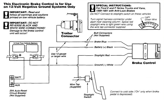
Wiring Guides from hopkinstowingsolutions.com Generic electric brake wiring diagram for dash mounted brake controller & trailer mounted tap brakemaster electric breakaway kit. It reveals the parts of the circuit as streamlined forms, as well as the power and signal connections in between the gadgets. Trailer electric brake wiring diagram from www.hhrvresource.com print the wiring diagram off plus use highlighters in order to trace the signal. Do not disturb the position of the switch. Variety of trailer breakaway wiring schematic. The 5th pin, a blue wire, gives power to operate (or disable) the trailer brakes. You may be in a position to learn specifically if the tasks should be completed, which makes it easier to suit your needs to properly control your time. $ wiring kit for 6 to 8 brake control systems, includes 25 ft.
Each component ought to be set and connected with different parts in particular manner.
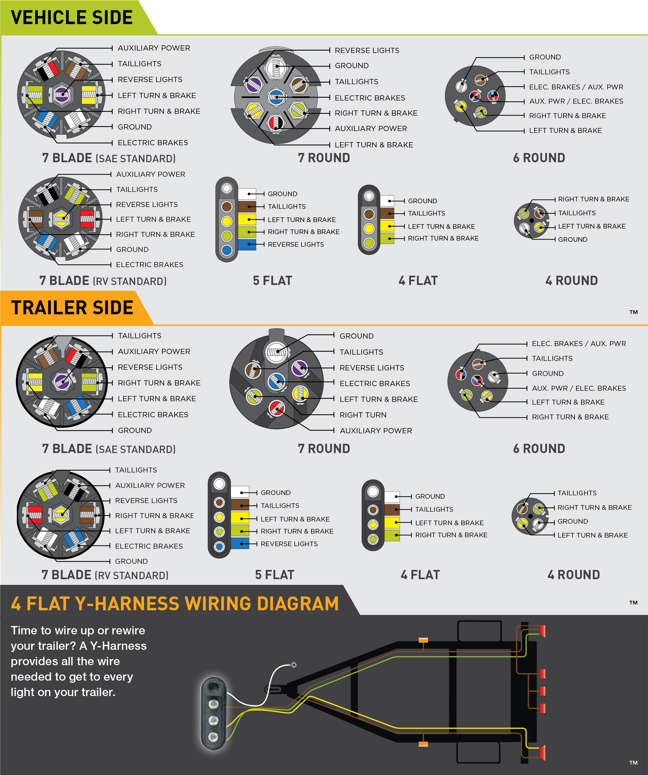
7 way plug wiring diagram standard wiring* post purpose wire color tm park light green (+) battery feed black rt right turn/brake light brown lt left turn/brake light red s trailer electric brakes blue gd ground white a accessory yellow this is the most common (standard) wiring scheme for rv plugs and the one used by major auto manufacturers today. The black wire is the power supply line to the brake control. Each component should be set and connected with different parts in specific way. Trailer electric brake wiring diagram from www.hhrvresource.com print the wiring diagram off plus use highlighters in order to trace the signal. We then run a jumper wire from the electric brake power wire to the right side brake assemblies (see photo). Elecbrakes must be connected to trailer wiring circuits as outlined in the wiring diagram. A wiring diagram is a simplified conventional photographic depiction of an electric circuit. White pin for the ground. Electric trailer brake wiring and parts diagrams click here to shop for electric trailer brakes and brake parts the two main types of electric brake assemblies for axles 7k and below are forward self adjusting (fsa) and manual adjusting. A wiring diagram is a streamlined conventional pictorial representation of an electric circuit. As the name implies, they use four wires to carry out the vital lighting functions. They also provide a wire for a ground connection. A wiring diagram is a streamlined traditional pictorial representation of an electrical circuit.
Of transportation requires that trailers equipped with brakes have a trailer break away system for activation of the trailer brakes, in the event that the trailer should become detached from the tow vehicle during highway travel. Trailer wiring connectors various connectors are available from four to seven pins that allow for the transfer of power for the lighting as well as auxiliary functions such as an electric trailer brake controller, backup lights, or a 12v power supply for a winch or interior trailer lights. White pin for the ground. It reveals the elements of the circuit as streamlined forms, and also the power and signal connections between the gadgets. The black wire is the power supply line to the brake control.
Trailer Wiring Diagrams For Single Axle Trailers And Tandem Axle Trailers from i2.wp.com It also talks about electric brake controller.thanks for watching ! Each component should be set and connected with different parts in specific way. Trailer wiring diagrams trailer wiring connectors various connectors are available from four to seven pins that allow for the transfer of power for the lighting as well as auxiliary functions such as an electric trailer brake controller, backup lights, or a 12v power supply for a winch or interior trailer lights. Properly wired control, voltage output to brakes and connection to trailer. Following the wiring diagram included with the controller, run the blue wire through the firewall and to the rear of the vehicle where it will connect to the trailer connector. $ wiring kit for 6 to 8 brake control systems, includes 25 ft. Of transportation requires that trailers equipped with brakes have a trailer break away system for activation of the trailer brakes, in the event that the trailer should become detached from the tow vehicle during highway travel. The red (stoplight) wire must be connected to the cold side of the brake pedal stoplight switch.
Duplex wire, 20 amp circuit breaker and attaching terminals.
Each component should be set and connected with different parts in specific way. Following the wiring diagram included with the controller, run the blue wire through the firewall and to the rear of the vehicle where it will connect to the trailer connector. We then run a jumper wire from the electric brake power wire to the right side brake assemblies (see photo). If a trailer has brakes, then it needs a connector with at least 5 pins. The 5th pin, a blue wire, gives power to operate (or disable) the trailer brakes. Assortment of electric trailer brake wiring schematic. A wiring diagram is a streamlined conventional pictorial representation of an electric circuit. If not, the arrangement will not function as it ought to be. Variety of trailer breakaway wiring schematic. Properly wired control, voltage output to brakes and connection to trailer. Duplex wire, 20 amp circuit breaker and attaching terminals. White pin for the ground. Trailer wiring connectors various connectors are available from four to seven pins that allow for the transfer of power for the lighting as well as auxiliary functions such as an electric trailer brake controller, backup lights, or a 12v power supply for a winch or interior trailer lights.
If a trailer has brakes, then it needs a connector with at least 5 pins. This dexter trailer brakes wiring diagram model is more suitable for sophisticated trailers and rvs. Generic electric brake wiring diagram for dash mounted brake controller & trailer mounted tap brakemaster electric breakaway kit. A wiring diagram is a streamlined traditional pictorial representation of an electrical circuit. A wiring diagram is a streamlined conventional pictorial representation of an electric circuit.
Trailer Brake Control Wiring Diagram from www.easternmarine.com You may be in a position to learn specifically if the tasks should be completed, which makes it easier to suit your needs to properly control your time. As the name implies, they use four wires to carry out the vital lighting functions. A wiring diagram is a streamlined conventional pictorial representation of an electric circuit. $ wiring kit for 6 to 8 brake control systems, includes 25 ft. Trailers with electric brakes need them too. Each component should be set and connected with different parts in specific way. The four wires control the turn signals, brake lights and taillights or running lights. Duplex wire, 20 amp circuit breaker and attaching terminals.
A wiring diagram is a streamlined conventional pictorial representation of an electric circuit.
This dexter trailer brakes wiring diagram model is more suitable for sophisticated trailers and rvs. It reveals the elements of the circuit as streamlined forms, and also the power and signal connections between the gadgets. It also talks about electric brake controller.thanks for watching ! Generic electric brake wiring diagram for dash mounted brake controller & trailer mounted tap brakemaster electric breakaway kit. $ wiring kit for 6 to 8 brake control systems, includes 25 ft. Splice down line from the switch; A wiring diagram is a simplified conventional photographic depiction of an electric circuit. 7 way plug wiring diagram standard wiring* post purpose wire color tm park light green (+) battery feed black rt right turn/brake light brown lt left turn/brake light red s trailer electric brakes blue gd ground white a accessory yellow this is the most common (standard) wiring scheme for rv plugs and the one used by major auto manufacturers today. You almost certainly know already that primus brake controller wiring diagram is among the top issues online. The black wire is the power supply line to the brake control. If a trailer has brakes, then it needs a connector with at least 5 pins. Collection of wiring diagram for utility trailer with electric brakes. Elecbrakes must be connected to trailer wiring circuits as outlined in the wiring diagram.