Home
› Logic Diagram And Truth Table Of Jk / Jk Flip Flop Diagram Truth Table Excitation Table Gate Vidyalay - The logic diagram consists of gates and symbols that can directly replace an expression in boolean arithmetic.
Logic Diagram And Truth Table Of Jk / Jk Flip Flop Diagram Truth Table Excitation Table Gate Vidyalay - The logic diagram consists of gates and symbols that can directly replace an expression in boolean arithmetic.
Logic Diagram And Truth Table Of Jk / Jk Flip Flop Diagram Truth Table Excitation Table Gate Vidyalay - The logic diagram consists of gates and symbols that can directly replace an expression in boolean arithmetic.. Each row will have different predetermined values as the truth table normally would have. Please help me solve this problem!!! These values will be like a standard truth table (in order by binary counting) ex/ and logic: Computers are based on electrical circuits where we can detect whether current is flowing or not. When a logic gate has only two inputs, or the logic circuit to be analyzed has only one or two gates, it is fairly easy to remember how a.
The rows of a basic truth table contain the boolean logic true or false values, while the columns list the premises of a scenario as well as the conclusion. You can see in the circuit diagram the inputs are connected to the outputs or it takes the output. There are a number of different logic gates that are each designed to perform a different operation in terms of output. Using the circuit diagram below, write the logic expression at the output of each gate until you reach the output of the circuit. These values will be like a standard truth table (in order by binary counting) ex/ and logic:
Conversion Of Flip Flops From One To Another Electronics Club from electronics-club.com There are a number of different logic gates that are each designed to perform a different operation in terms of output. Logic tells us that if two things must be true in order to proceed them both condition_1 and condition_2 must be true. Logic diagrams and truth tables. The rows of a basic truth table contain the boolean logic true or false values, while the columns list the premises of a scenario as well as the conclusion. A logic gate is a device that can perform one when combined, several gates can make a complex logical evaluation system that has many inputs and outputs. Logic gates and truth tables. Master slave flip flop circuit electronic circuits and diagrams. You can enter logical operators in several different formats.
A venn diagram is, in essence, a visual truth table.
In engineering, our goal is to produce electric circuits that can implement the behavior an example of a circuit that can implement the operation $f=a\cdot b$ is shown in the diagram in fig. Truth tables summarize how we combine two logical conditions based on and, or, and not. Each row will have different predetermined values as the truth table normally would have. Logic gate circuits are most frequently symbolized with a schematic diagram through their own exclusive symbols instead of their essential resistors and. Logic diagrams and truth tables. A.) f=x' y+y z' (x y z) b.) g=a c+ b' c+ a' b. Introduction to state table, state diagram & state equation. Surprisingly, this handful of definitions will cover the majority of logic. The rows of a basic truth table contain the boolean logic true or false values, while the columns list the premises of a scenario as well as the conclusion. The tables above show us the truth tables of jk flip flop with: This tool generates truth tables for propositional logic formulas. There are a number of different logic gates that are each designed to perform a different operation in terms of output. You can enter logical operators in several different formats.
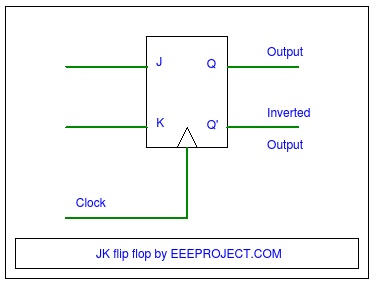
When a logic gate has only two inputs, or the logic circuit to be analyzed has only one or two gates, it is fairly easy to remember how a. Jk flip flop construction, logic circuit diagram, logic symbol, truth table, characteristic equation & excitation table are discussed. Because q and q are always different, we can use the outputs to control the. When both inputs j and k are equal to logic 1, the jk flip flop toggles as shown in the following truth table. Introduction to state table, state diagram & state equation.
Jk Flip Flop Explained In Detail from eeeproject.com Draw the truth table for a logic function that takes a three bit binary number and produced an output that is 0 for even parity and 1 for odd parity. We title the first column p for biconditional truth table. Truth tables summarize how we combine two logical conditions based on and, or, and not. Because q and q are always different, we can use the outputs to control the. Logic gate circuits are most frequently symbolized with a schematic diagram through their own exclusive symbols instead of their essential resistors and. The symbol and truth table of a not gate with one input is shown below. When the switches are both closed, the. The s and r inputs of the rs bistable have been replaced by the two inputs called.
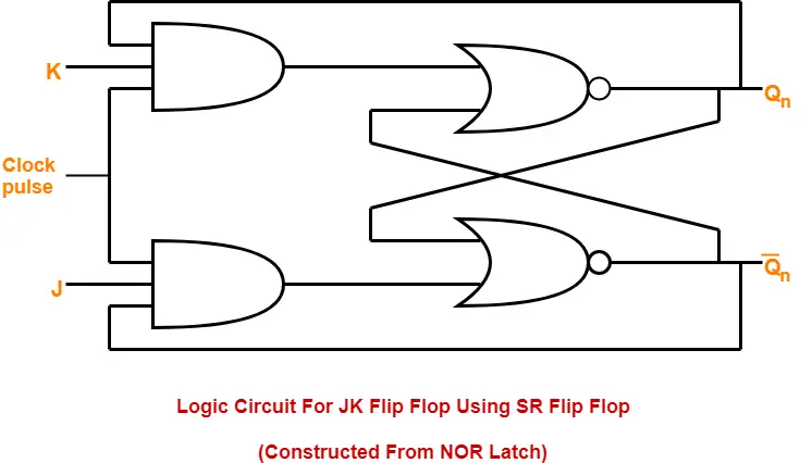
The s and r inputs of the rs bistable have been replaced by the two inputs called.
The jk flip flop is basically a gated rs flip flop with the addition of the clock input circuitry. The user inputs the output values in the x column it will be a chart much like this Each row will have different predetermined values as the truth table normally would have. By using this gate, we can implement nor and nand gates. Draw the truth table for a logic function that takes a three bit binary number and produced an output that is 0 for even parity and 1 for odd parity.
Jk Flip Flop Diagram Truth Table Excitation Table Gate Vidyalay from www.gatevidyalay.com These values will be like a standard truth table (in order by binary counting) ex/ and logic: When the switches are both closed, the. Featuring a purple munster and a duck, and optionally showing intermediate results, it is one of the better instances of its kind. There are a number of different logic gates that are each designed to perform a different operation in terms of output. How to draw the logic diagram for this? This tool generates truth tables for propositional logic formulas. When a logic gate has only two inputs, or the logic circuit to be analyzed has only one or two gates, it is fairly easy to remember how a. A.) f=x' y+y z' (x y z) b.) g=a c+ b' c+ a' b.
In engineering, our goal is to produce electric circuits that can implement the behavior an example of a circuit that can implement the operation $f=a\cdot b$ is shown in the diagram in fig.
When a logic gate has only two inputs, or the logic circuit to be analyzed has only one or two gates, it is fairly easy to remember how a. At the most elementary level, an elecrtonic device can only recognise the presence or absence of current or voltage. Does my truth table correct? The notation may vary depending on what industry you're engaged in, but the basic concepts are the same. The symbol and truth table of a not gate with one input is shown below. The s and r inputs of the rs bistable have been replaced by the two inputs called. Truth table is a mathematical table and the base for all computing needs. Truth tables, logic, and demorgan's laws. We title the first column p for biconditional truth table. Jk flip flop diagram truth table excitation table gate. Logic diagrams and truth tables. The rows of a basic truth table contain the boolean logic true or false values, while the columns list the premises of a scenario as well as the conclusion. Jk flip flop construction, logic circuit diagram, logic symbol, truth table, characteristic equation & excitation table are discussed.